
Control the Basic ESC with a Potentiometer and Arduino
By Daniel
Introduction
This guide will show you how to use a potentiometer and an Arduino to control the Basic ESC. It builds from our Basic ESC R3 Example Code for Arduino so if you haven’t already, make sure to check that out first.Parts and Tools
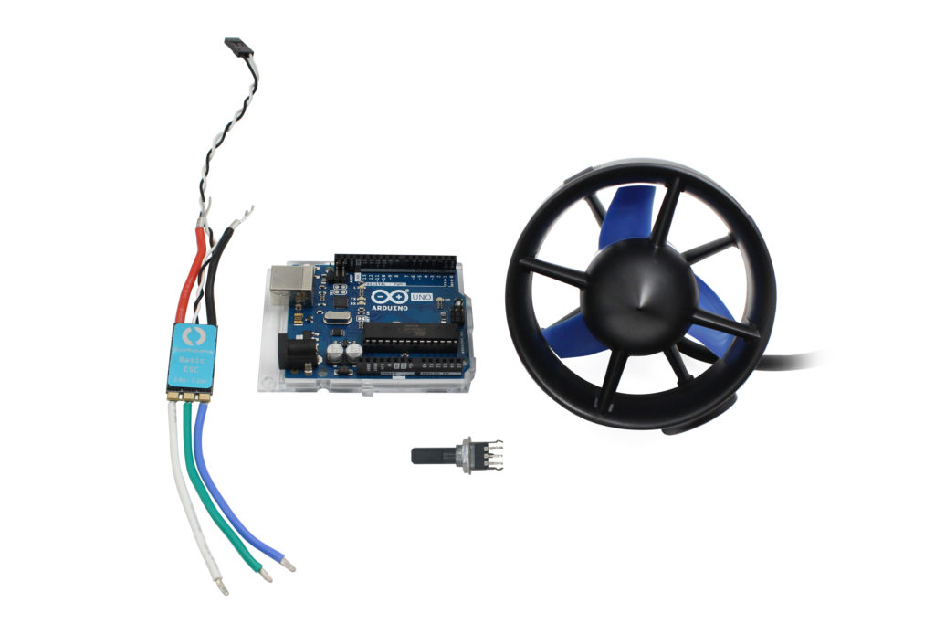
Main components used in this guide.
You Will Need
- Arduino Microcontroller (This tutorial uses an Arduino Uno)
- 1 x 10k ohm Potentiometer (center detent recommended)
- 1 x USB A to B cable (to connect your Arduino to a computer)
- 2 x male to male Jumper Wires
- 3 x male to female Jumper Wires
- 1 x 3-position terminal strip connector (to connect the ESC to the thruster)
- 1 x Terminal Block (for power distribution)
- Battery or Power Source for ESC/thruster (a T200 has a maximum voltage rating of 20V DC)
- Arduino IDE
Video Tutorial
Wire Connections
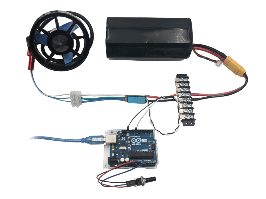
All the components connected.
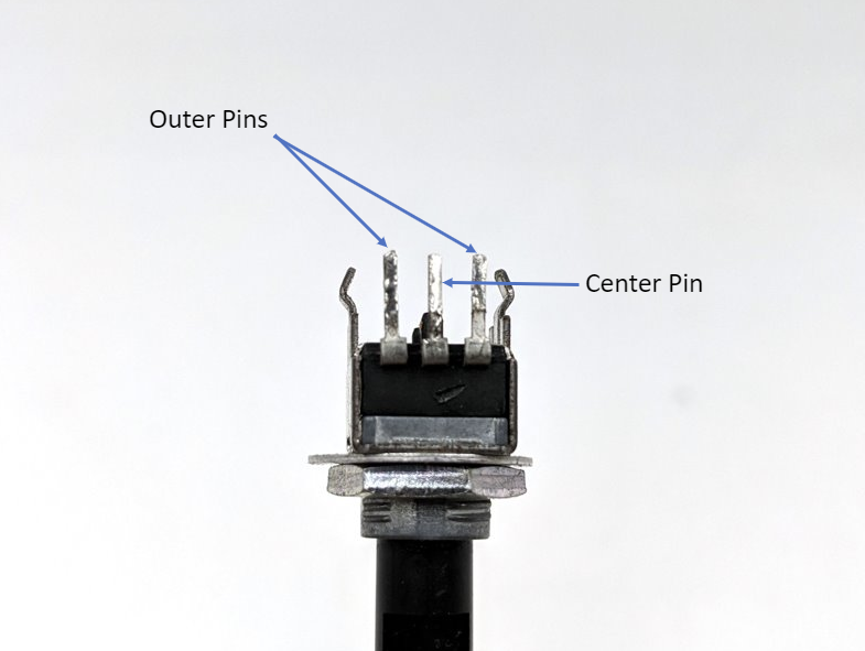
Connecting the Potentiometer
- A potentiometer will have 3 pins, the two outer pins will connect to 5V and ground and the center pin will connect to an analog input.
- Connect one of the outer pins to 5V on the Arduino using a male to female jumper wire.
- Connect the other outer pin on the potentiometer to ground on the Arduino using a male to female jumper wire.
- Connect the center pin on the potentiometer to one of the analog in pins on the Arduino using a male to female jumper wire. In this example we’re using pin A0.
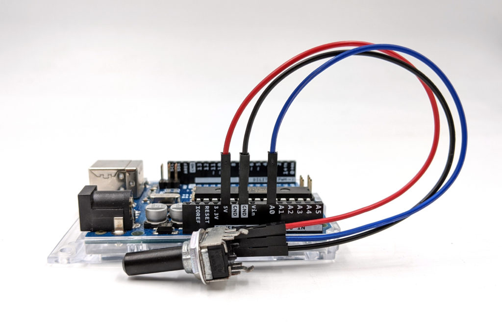
Potentiometer connected to the Arduino.
Connecting the ESC
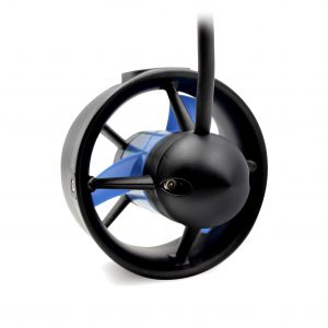
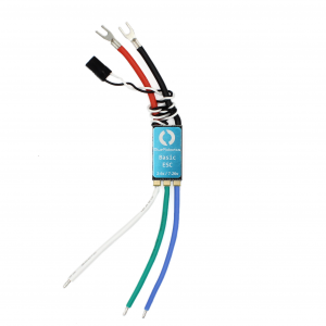
- Connect your thruster to the ESC by matching the green, white, and blue wires from the ESC to the green, white, and blue wires from the thruster.
- Connect the white signal wire from the ESC to digital pin 9 using a male to male jumper wire.
- Connect the black (ground) wire from the ESC to a ground pin on the Arduino using a male to male jumper wire.
- Connect the ESC to your power source.
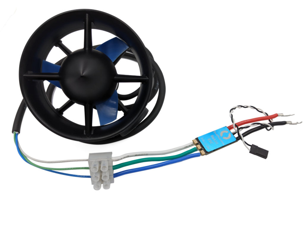
ESC motor wires to thruster.
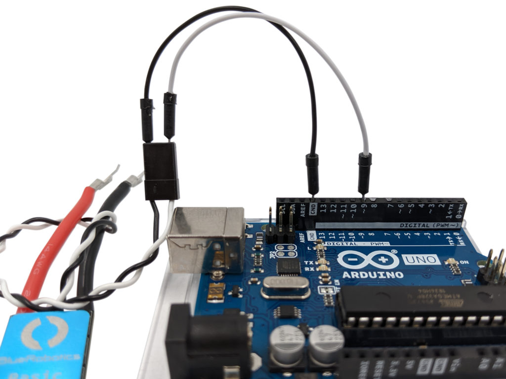
ESC signal wires connected to the Arduino.
Using the Example Sketch
- Connect your Arduino to the computer with the USB cable.
- Copy the code from the example sketch into a new sketch in the Arduino IDE.
- Make sure the potentiometer knob is turned to the center position.
- Upload the sketch to the Arduino.
- That’s it! If everything is working correctly you should hear the ESC arm after a few seconds. You can now control the throttle, forward and reverse, with the potentiometer.
#include <Servo.h>

byte servoPin = 9; // signal pin for the ESC.
byte potentiometerPin = A0; // analog input pin for the potentiometer.
Servo servo;

void setup() {
servo.attach(servoPin);
servo.writeMicroseconds(1500); // send "stop" signal to ESC. Also necessary to arm the ESC.

delay(7000); // delay to allow the ESC to recognize the stopped signal.
}

void loop() {

int potVal = analogRead(potentiometerPin); // read input from potentiometer.

int pwmVal = map(potVal,0, 1023, 1100, 1900); // maps potentiometer values to PWM value.

servo.writeMicroseconds(pwmVal); // Send signal to ESC.
}
If the thruster is spinning in the wrong direction you can just switch two of the motor wires (blue, green, white wires).
Troubleshooting
- The ESC doesn’t arm after uploading the sketch:
- If the Arduino was powered on before the ESC then the ESC might have missed the arming signal. Either restart the Arduino or return the potentiometer to the center position to send the correct arming signal.
Authors

Daniel
Daniel is a Technical Support Specialist at Blue Robotics and is an expert at working with all elements of our product line!