
Turning a Thruster On and Off with a Thruster Commander
By Kevin
Parts and Tools
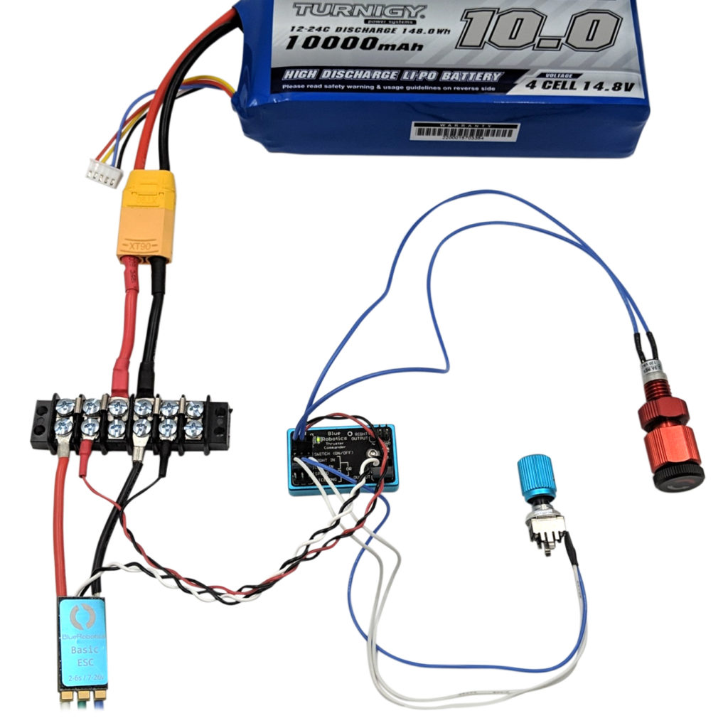
All of the components used in this guide.
You Will Need
You will also need:
- 1 x 0.1″ (2.54mm) Crimp Connector Housing: 1×3-Pin
- 2 x Female Crimp Pins for 0.1″ Housings
- 1 x Universal Wire Terminal Crimping Tool
- 1 x Wire Stripper, 30-20 Gauge Maximum Cutting Capacity
- 1x LiPo or Li-Ion 4S Battery
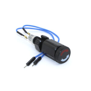
Switch Assembly
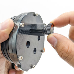
Follow the instructions in the Switch installation guide to properly assemble the Switch. The endcap is not required for this guide.
Switch Installation
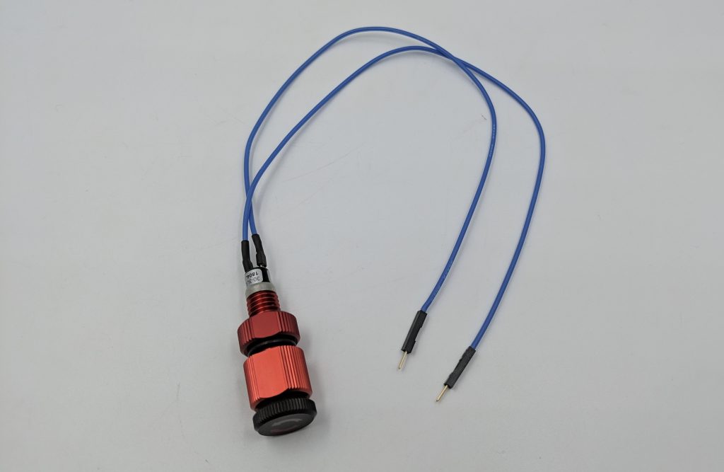
The end result should be a completed Switch in its stock configuration as pictured below.
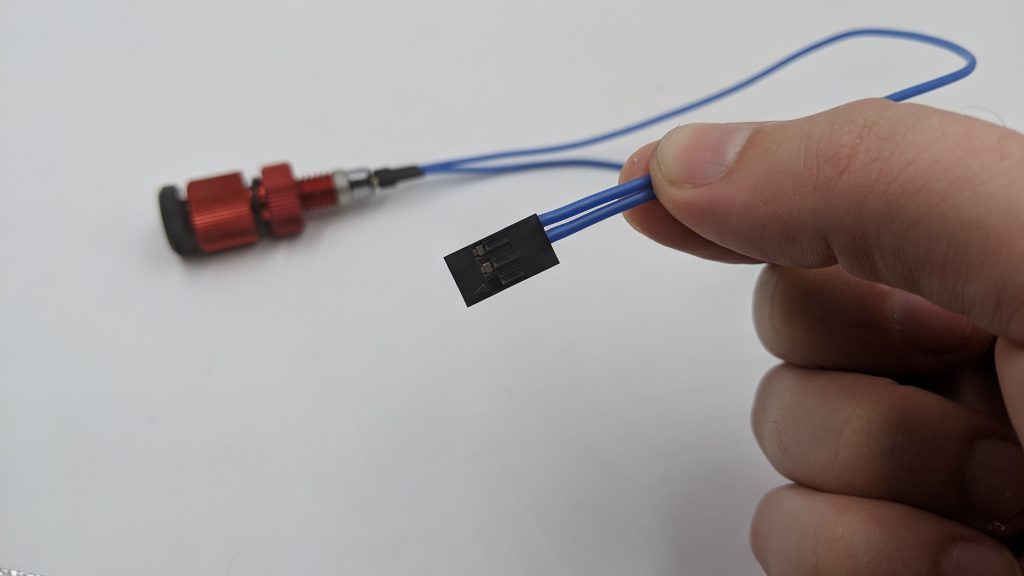
Switch Connector Modification
In its stock configuration, the Switch is not compatible with a Thruster Commander and female pins will need to be installed instead of the pre-installed male pins. to do so, you will need the following parts and tools:
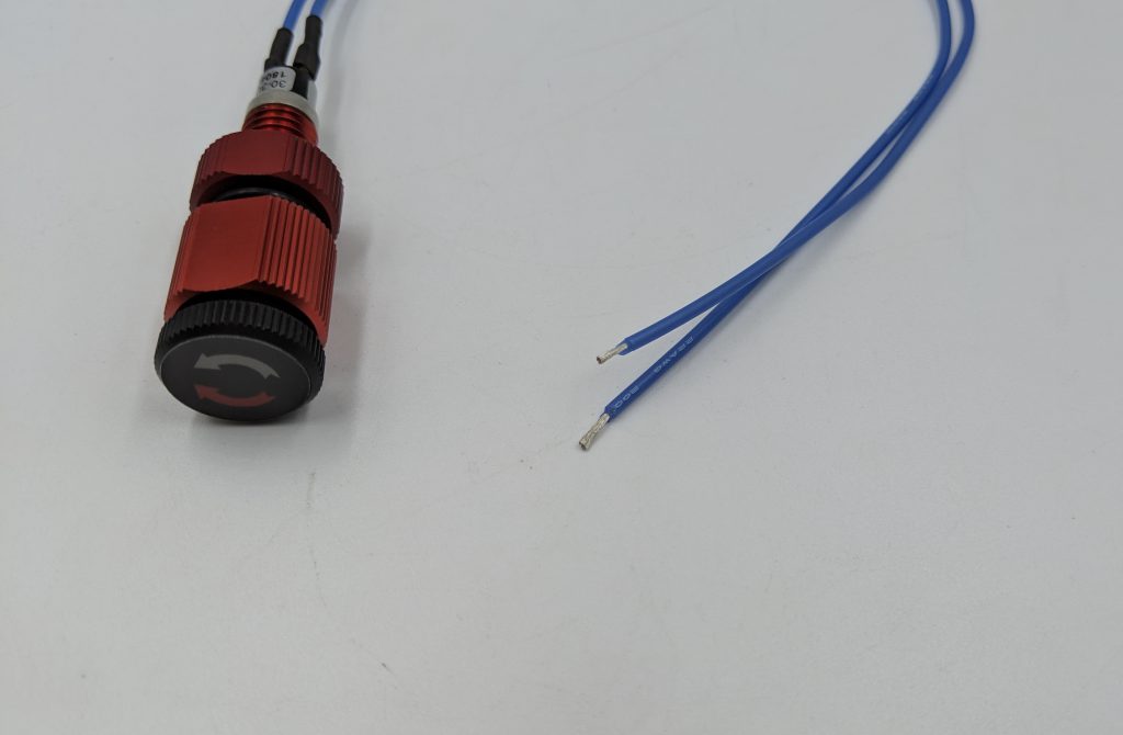
1. Cut off the male crimp pins and their single pin housings from both wires. Strip about 5 mm of blue jacket off each of the wire ends.
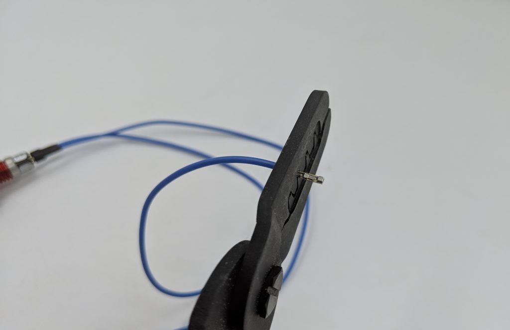
2. Using the Wire Terminal Crimping Tool install a female crimp pin onto each stripped wire end ensuring the wire is securely crimped in place.
3. Push the wires into the 3-position 0.1″ (2.54mm) Crimp Connector Housing with one wire going into one of the outer positions and the other going into the middle position.
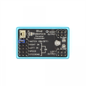
Thruster Commander Wire Assembly
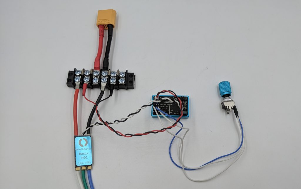
1. Follow the instructions in the Thruster Commander guide to properly assemble the wiring for power, signal wires and ESC. The specific section is “Connecting the Battery and ESCs.” For this guide, we will only be using one ESC and thruster so the left or right side may be chosen. An additional ESC and thruster may be added if desired.

Guide to the Thruster Commander
2. Connect one of the potentiometers to the “SPEED” input pins.
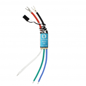
3. Connect a 3-position terminal block that comes with the Thruster Commander kit to the end of the ESC phase wires. Connect the thruster phase wires to the corresponding terminal block.
4. The result should be a Thruster Commander assembly in the configuration as pictured below.
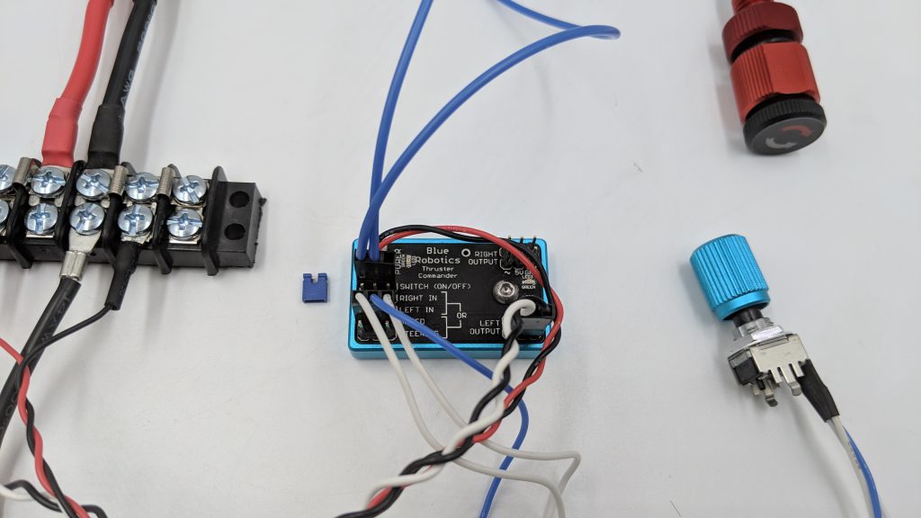
5. Remove the blue jumper from the “SWITCH (ON/OFF)” input.
6. Install the 3-position female crimp housing onto the SWITCH input. One wire must be connected to the ground (GND) and the other connected to the center pin (~). The right most pin (5V) is left bare and not connected to any wire.
Operation
1. Open the Switch by twisting the knob to the left until it is no longer in the threads. Do not remove the knob from the penetrator.
2. Center the SPEED potentiometer. The center midpoint can be found by sweeping the knob left and right.
3. Connect a battery to the XT90 connector and power on the system. Five high pitched beeps will be heard from the thruster windings. Additional information on ESC initialization can be found in the Thruster Commander guide: Operation – ESC Initialization.
4. With the potentiometer centered (neutral), close the Switch by turning it all the way to the right until it stops and is secured.
5. Twist the SPEED potentiometer knob a few degrees (not full to the stops) and the thruster should begin to turn one direction.
6. Twist the Switch to the right until the switch opens and turns off the thruster. Twist the switch to the left to turn the thruster back on at the indicated speed setting without having to adjust the SPEED potentiometer.
7. That’s it! The whole assembly can be installed in a WTE or waterproof box to keep your components dry.
Authors

Kevin
Kevin is the Applications Engineer at Blue Robotics. He has a love for marine robotics and explorations and was one of Blue Robotics' first Kickstarter backers in 2014! Since then he's joined our team and helps fellow explorers around the world use Blue Robotics products to accomplish their missions.