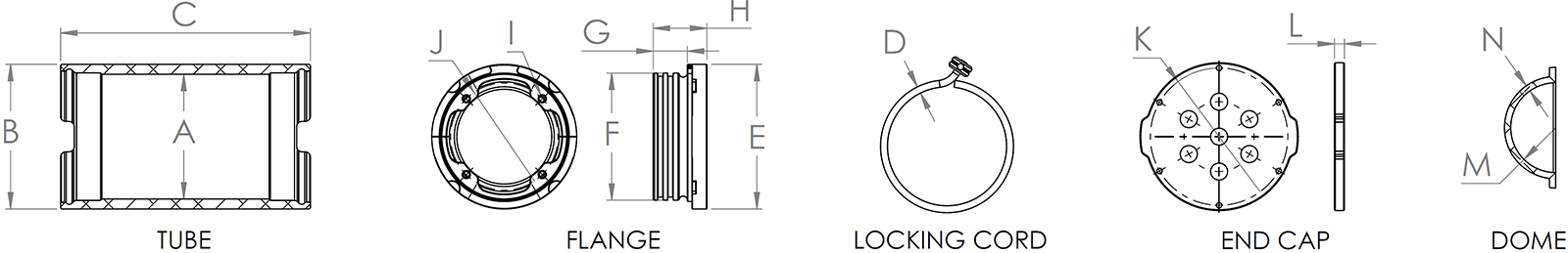
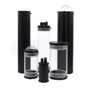
Meet our second generation 2″, 3″, 4″, 5″, 6″, and 8″ Series watertight enclosures for ROVs, AUVs, marine vehicles, and other harsh environments. They’re completely configurable with a variety of tube and end cap options offering a substantial upgrade over the first generation of watertight enclosures. Precision machined O-ring interfaces, a locking cord and anti-rotation feature to secure the flange, and smooth O-ring lead-in make these enclosures a perfect fit for a wide range of applications including MATE and Robosub ROVs, subsea batteries, cameras, electronics, data loggers, environmental monitoring, instrument housings, junction boxes, and more.
When used with the clear acrylic plastic tube option, it’s easy to see the components inside the enclosure, ideal for subsea development projects and research ROVs and AUVs. The aluminum tube option provides a greater depth rating, opaque appearance, and better thermal transfer for high power applications like power supply housings and battery housings.